
An Easy Introduction to Sheet Metal Design in CAD for Beginners
- Bk Engineering
- Feb 19, 2024
- 6 min read

Updated: Mar 26
Table of Content
Forming Basics
What is Sheet Metal Design in CAD?
Sheet Metal Fabrication is the process of forming parts from a metal sheet by punching, cutting, stamping, and bending.
3D CAD files are converted into machine code, which controls a machine to precisely cut and form the sheets into the final part.
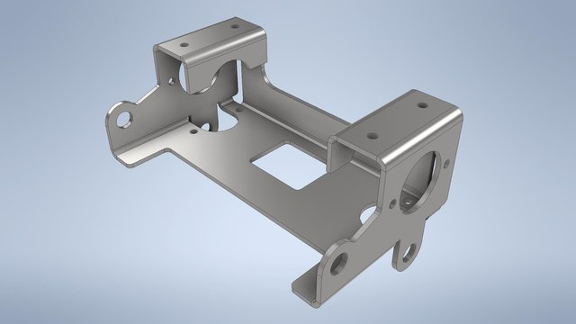
Sheet metal parts are known for their durability, which makes them great for end use applications (e.g. chassis).
Parts used for low volume prototypes, and high volume production runs are most cost-effective due to large initial setup and material costs.
Because parts are formed from a single sheet of metal, designs must maintain a uniform thickness.
Be sure to follow the design requirements and tolerances to ensure parts fall closer to design intent and cutting sheets of metal
Sheet Metal Design Software Options
Sheet metal parts can be designed in many different CAD (Computer Aided Design) programs. Some of the most popular options for sheet metal design are:
SolidWorks – Widely used with features like flanges, gauges, and flat pattern conversion.
AutoCAD – General-purpose CAD with a dedicated sheet metal toolkit.
Inventor – Robust Autodesk software with flange, bend, and corner treatments.
NX – High-end Siemens CAD for complex sheet metal components.
Creo – Offers parametric modeling with sheet metal-specific functions.
Fusion 360 – Provides flanges, rules, and flat pattern views.
Sheet Metal Design Process Overview
The typical workflow for designing sheet metal parts in CAD follows these key stages:
3D Part Modeling
Use sheet metal tools in CAD to create a parametric model with features like flanges, bends, cutouts, reliefs, and hems. Ensure the design follows manufacturing constraints.
Define Sheet Metal Parameters
Set critical properties such as material thickness,
bend radius, K-factor, bend allowances, and reliefs.
These parameters control how the material behaves during bending.When creating a new part file, you'll want to specify that it is a "Sheet Metal" part. This activates specialized sheet metal features and tools. You can set material properties like steel, aluminum, etc. The material impacts forming simulations.

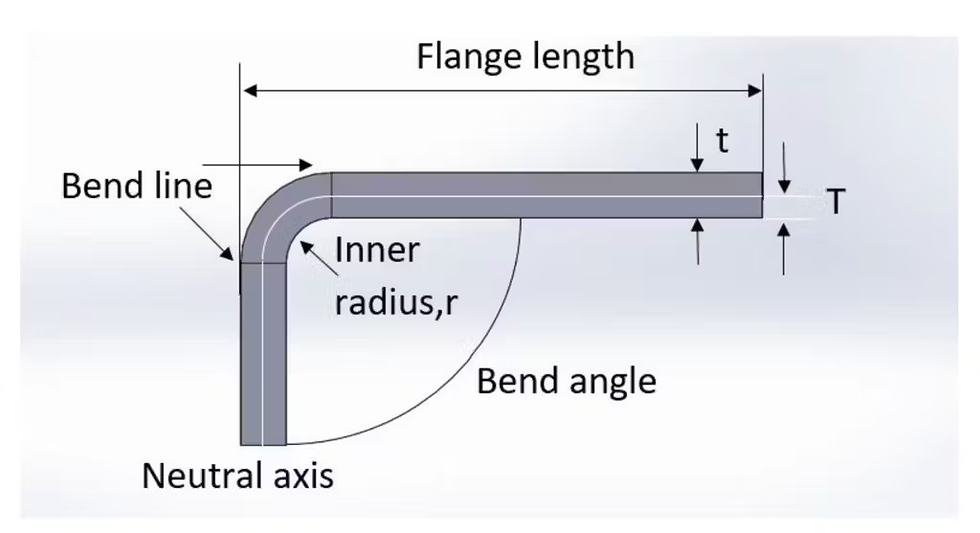
Bend line– A bend line is a reference line in sheet metal design that indicates where a bend will occur. It is used in flat patterns to guide the bending process and ensure accurate part formation.
Bend radius – is the distance from the center of a bend to the inner surface of the material being bent. It determines how sharp or smooth the bend is A smaller bend radius creates a sharper bend. larger bend radius results in a smoother, more gradual bend.
The minimum bend radius depends on the material type and thickness to prevent cracking or deformation.
Bend angle – is the angle formed between the two sides of a bent sheet metal part, measured from the inside of the bend. It determines how much the material is bent.
Neutral axis – The neutral axis is an imaginary line within a material undergoing bending where there is no compression or tension. It separates the compressed inner side from the stretched outer side of the bend.
K-factor – The location of the neutral axis in the material, calculated as the ratio of the distance of the neutral axis T, to the material thickness t. The K-factor is dependent upon several factors (material, bending operation, bend angle, etc.) and is greater than 0.25, but cannot exceed 0.50. K factor = T/t
The K-factor is the ratio between the the neutral axis to the thickness of the material.

Importance of the K-factor in sheet metal design

K - Factor Chart. The K-factor is used to calculate flat patterns because it is related to how much material is stretched during bending. Therefore it is important to have the value correct in CAD software. The value of the K-factor should range between 0 – 0,5. To be more exact the K-factor can be calculated taking the average of 3 samples from bent parts and plugging the measurements of bend allowance, bend angle, material thickness and inner radius into the following formula:

Some basic K-factor values are shown here. Use these as a guideline.

Bend allowance – The length of the neutral axis between the bend lines or the arc length of the bend. The bend allowance added to the flange lengths is equal to the total flat length.
Material Thickness - is the measurement of the distance between the two outer surfaces of a sheet metal piece. It determines the strength, flexibility, and suitability of the material for different manufacturing processes.Doubling the thickness does not mean doubling the tonnage. Instead the bending force is related by the square of the thickness. What this means is that if the material thickness is doubled the tonnage required increases 4 fold.
Hems: The Principle of Hemming

A hem is a folded edge of a sheet metal part, created by bending the material back onto itself. It is used to reinforce edges, eliminate sharp edges, and improve part safety and strength.
Types of Hems:
Open Hem – Leaves a small gap between the folded layers.
Closed Hem – Folds completely onto itself with no gap.
Teardrop Hem – Forms a rounded loop to prevent cracking in thicker materials.
Hems are commonly used in automotive, aerospace, and appliance manufacturing for durability and safety.
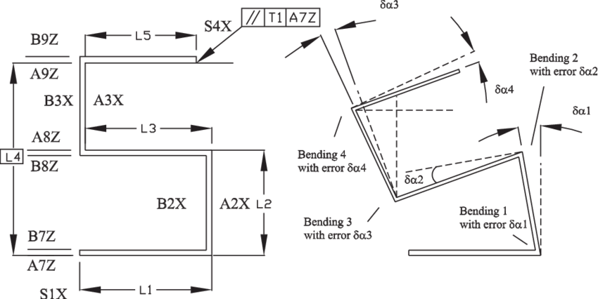
Bend Relief

A bend relief is a small cut or notch added at the edge of a sheet metal part to prevent tearing or deformation when bending. It allows the material to bend smoothly without creating unwanted cracks or distortions. Bend relief is especially useful when a bend is close to an edge.
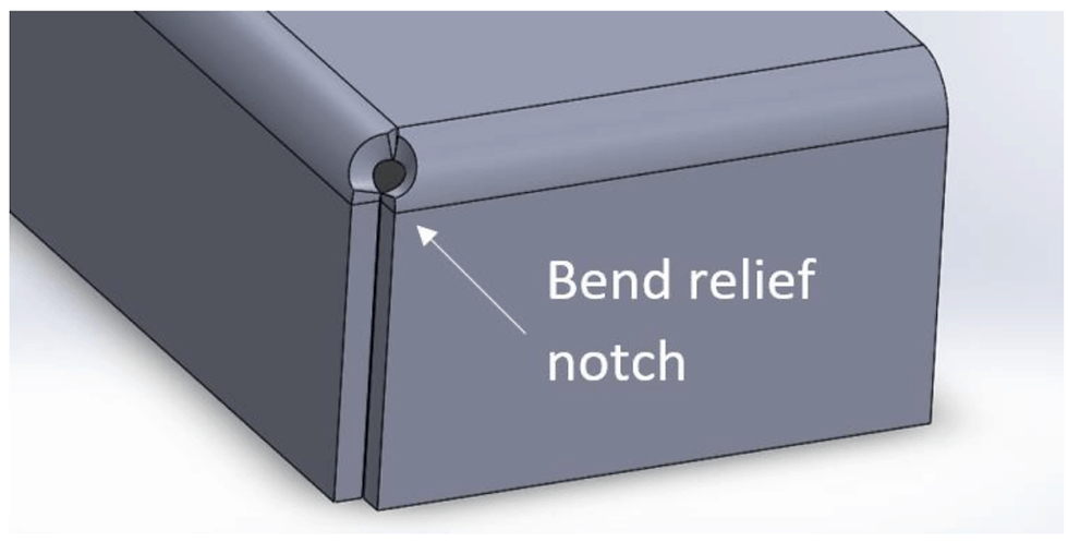
It can be a simple notch, a rounded cut, or a rectangular cut, depending on the design needs.
When a bend is made close to an edge the material may tear unless bend relief is given.
Bend 1 shows a a tear relief.
Bend 2 shows a rectangular relief cut into the part, the depth of the relief should be greater than the radius of the bend. The width of the relief should be the material thickness or greater.
Seams and Joints
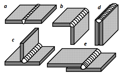
Lap Joint – One sheet overlaps another; common in welding and fastening.
Butt Joint – Two edges meet without overlap; used in welding.
Lock Seam – Edges are folded together for a secure, strong connection.
Pittsburgh Seam – Used in HVAC ducts for airtight sealing.
Corner Joint – Connects sheets at a 90° angle, often welded.
Cutouts, Holes, Lances, and Slots
Cutouts – Open areas removed from a sheet, often for weight reduction, ventilation, or clearance.
Holes – Circular openings used for fasteners, rivets, or drainage.
Lances – Cuts that create a tab without material removal, used for ventilation or hooks.
Slots – Elongated holes for adjustable fasteners or component alignment.
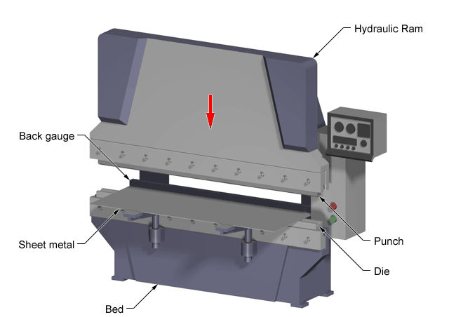
Bending
Bending is a process whereby a force is applied to sheet metal which causes it to bend at an angle and form the desired shape. Bends can be short or long depending on what the design requires.
Bending is performed by a press brake machine that can be automatically or manually loaded. Press brakes are available in a variety of different sizes and lengths (20-200 tons) depending on the process requirements.
Parts to be bent are supplied as flat patterns with bending information. Sometimes bend positions are etched with bend notches, or these notches can be cut out to show the benders where to bend.
Once the laser has cut the flat parts out they can be sent
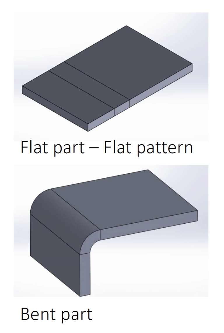
Flat Pattern Generation
Unfold the 3D model to create a 2D flat pattern. The CAD system calculates bend allowances and provides an accurate cut shape for fabrication.
Detailing & Annotations
Add bend lines, bend angles, dimensions, punch features, and material specifications in the drawing. These annotations help in manufacturing and quality checks.

DXF/DWG Export for CAM
Convert the flat pattern into DXF or DWG files for CNC cutting processes like laser cutting, plasma cutting, or waterjet cutting. These files ensure precise cutting paths.
Bend Simulation & Validation
Use CAD tools to simulate bending and check for design issues like interference, over-bending, and material stretching before sending it for production.
Conclusion
Sheet metal design in CAD is a fundamental skill for engineers and designers. By following best practices, considering material properties, and leveraging CAD tools, you can create efficient and manufacturable sheet metal parts. As a next step, explore advanced topics like louvering, dimpling, and hemming to enhance your designs.
Recommended Tutorials, Courses, and Books
The [SolidWorks Sheet Metal tutorials](https://www.solidworks.com/sw/resources/solidworks-tutorials/sheet-metal.htm) on the SolidWorks website cover the sheet metal workflow step-by-step. They're a great starting point for SolidWorks.
LinkedIn Learning has an online course called [SOLIDWORKS: Sheet Metal](https://www.linkedin.com/learning/solidworks-sheet-metal-essential-training-2) that comprehensively teaches the sheet metal tools.
For AutoCAD, check out the [Sheet Metal Design tutorials](https://knowledge.autodesk.com/support/autocad/learn-explore/caas/simplecontent/content/sheet-metal-design-tutorials.html) on the Autodesk website.
The book Sheet Metal Design in Inventor 2022 by Lokseva Publishing offers detailed explanations of the sheet metal tools in Inventor.
For NX CAD, the book Sheet Metal Design using NX 12 by CADCAM BOOKS is a great resource.


Comments