Mechanical Engineer's Guide to Reverse Engineering
- Subramanya Charan
- Mar 10
- 4 min read
Updated: 1 day ago

Introduction to Reverse Engineering
Reverse engineering is the process of deconstructing a product or system to understand its design, functionality, and components. It is commonly used in industries like manufacturing, automotive, aerospace, and product design. Engineers analyze an existing product to recreate, improve, or modify it based on their requirements.
Why is Reverse Engineering Important?
Reverse engineering has several practical applications, such as:
Product Improvement – Helps redesign a product to enhance its functionality, durability, or cost-effectiveness.
Replacement of Legacy Parts – When original designs are unavailable, reverse engineering helps recreate critical components.
Competitive Analysis – Helps companies understand competitors' products and incorporate improvements into their own designs.
Failure Analysis – Identifies design flaws or material weaknesses in a product.
Documentation – Generates detailed CAD models and drawings for future reference.
Tools and Equipment Needed
Before starting the reverse engineering process, engineers use various tools for measurement, analysis, and modeling. Some commonly used tools include:
Measurement Tools
Calipers and Micrometers – For accurate linear and diameter measurements.
Coordinate Measuring Machine (CMM) – For high-precision measurements of complex geometries.
3D Scanners – For capturing a digital model of a component quickly and accurately.
Material Analysis Tools
Hardness Testers – To determine material strength.
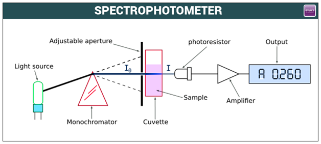
Spectrometers – To analyze the material composition.
Software Tools
CAD Software (SolidWorks, CATIA, AutoCAD, etc.) – For 3D modeling.
Simulation Software (ANSYS, ABAQUS, etc.) – For testing the product’s behavior under real-world conditions.

Defining the Objective
Before starting the reverse engineering process, clearly define why you are analyzing the product. Questions to consider:
What is the end goal? (Redesign, improvement, documentation, etc.)
What aspects of the product need analysis? (Geometry, material, performance, etc.)
Are there any legal restrictions on reverse engineering this product?
Initial Inspection and Documentation
Observe the product’s overall structure, shape, and functionality.
Identify key features and components.
Take detailed photographs and notes from different angles.
Check for any signs of wear, damage, or failure points.
Disassembly (If Applicable)

Carefully disassemble the product while documenting each step.
Label components to ensure proper reassembly if required.
Note fastener types, joint designs, and material properties.
Dimensional Analysis and Measurement
Measure key dimensions using calipers, micrometers, or CMM.
If complex geometries are involved, use 3D scanners for accurate digitization.
Convert physical dimensions into a rough 2D sketch for reference.
Material Analysis

Identify the material type using a spectrometer or hardness tester.
Analyze surface coatings or treatments.
Determine if alternative materials can improve performance.
CAD Modeling and 3D Reconstruction

This is one of the most critical steps in reverse engineering, where the collected data is converted into a 3D model.
Selecting the Right CAD Software
Choose software based on complexity and requirements:
SolidWorks, CATIA, NX – Suitable for mechanical components.
AutoCAD – Good for 2D sketches and simple 3D models.
Fusion 360 – Ideal for both CAD modeling and simulation.
Creating a Basic Sketch
Begin by sketching key profiles based on measured dimensions.
Use reference planes and constraints to define relationships between features.
Ensure the sketch is fully constrained before moving forward.
Converting Sketches into 3D Models
Use extrusion, revolve, loft, and sweep commands to create 3D features.
Apply fillets, chamfers, and draft angles as per the original design.
If scanned data is used, import the STL/STEP file into the CAD software and refine the geometry.
Assembling the Components
If the product consists of multiple parts, assemble them in the CAD software.
Use proper mates and constraints to simulate real-world movement.
Check for interferences or misalignments.
Generating Engineering Drawings
Once the 3D model is complete, create 2D manufacturing drawings.
Add necessary dimensions, tolerances, and GD&T symbols.
Ensure clear annotations for manufacturing feasibility.
Simulation and Analysis
Before manufacturing or prototyping, it’s essential to test the design under real-world conditions.
Structural Analysis – Check for stress, deformation, and failure points.
Thermal Analysis – Ensure the material can withstand high or low temperatures.
Motion Analysis – Simulate moving components to check for smooth operation.
Simulation tools like ANSYS, Abaqus, and SolidWorks Simulation help validate the design before production.
Prototyping and Testing
Once the CAD model is finalized and verified through simulation, a prototype is created.
3D Printing – Used for rapid prototyping and testing fitment.
CNC Machining – For producing functional metal prototypes.
Material Testing – Ensures the prototype meets strength and performance criteria.
Testing includes mechanical stress tests, functional tests, and real-world performance evaluations.
Documentation and Finalization
Prepare detailed CAD files and manufacturing drawings.
Document the material specifications, assembly procedures, and testing results.
Save all files in appropriate formats (STEP, IGES, PDF, DXF, etc.).
Create a final report summarizing the entire reverse engineering process.
Implementation and Continuous Improvement
If manufacturing, ensure proper quality control checks.
Gather feedback from testing and modify the design if needed.
Keep refining the product for better efficiency, cost reduction, or performance enhancement.
Common Challenges and How to Overcome Them
Inaccurate Measurements
Use high-precision tools like CMM or 3D scanners for complex geometries.
Missing Design Data
Reverse engineer similar products or refer to existing engineering standards.
Material Identification Issues
Conduct chemical composition tests and hardness testing.
Complex Surfaces in CAD Modeling
Used surface modeling techniques in SolidWorks or CATIA for intricate designs.
Legal and Ethical Concerns
Ensure compliance with patents and intellectual property laws before reverse engineering a product.


Comments