
GD&T: Fundamentals of Geometric Dimensioning and Tolerancing
- Bhargava Krishna Marripati

- May 25, 2023
- 13 min read
Updated: Mar 25

Table of Content
Introduction to Fundamentals of Geometric Dimensioning and Tolerancing (GD&T)
In the realm of engineering and manufacturing, ensuring the precise and accurate specification of product dimensions and tolerances is crucial for successful production. Fundamentals of Geometric Dimensioning and Tolerancing (GD&T) is a symbolic language that provides a comprehensive framework for defining and communicating engineering tolerances. This article serves as a complete guide to understanding GD&T and its applications in various industries.
What is GD&T?
GD&T is a system for defining and communicating engineering tolerances using symbolic language and standardized notation. It provides a clear and unambiguous method for specifying the permissible variation of geometric dimensions and features on a part or assembly. By using GD&T, engineers and manufacturers can effectively communicate design intent and ensure that products meet the required functionality and performance.
The Purpose of GD&T
The primary purpose of GD&T is to establish a common language for expressing tolerances and ensure consistent interpretation across different stages of the product lifecycle. It enables designers to clearly communicate their intent to manufacturing and inspection teams, reducing the likelihood of errors and misunderstandings. GD&T also facilitates interchangeability of parts, enhances product quality, and supports efficient manufacturing processes.
Key Concepts of GD&T
To understand GD&T, it is essential to grasp some key concepts that form the foundation of this system. These concepts include datums, geometric tolerances, and symbols represented by feature control frames.
`
Datums
Datums are reference points, planes, or axes identified on a part to establish a coordinate system. They provide a basis for measuring and tolerancing other features of the part.
Geometric Tolerances
Geometric Tolerances specify the allowable variation for geometric features such as form, orientation, location, and profile. These tolerances are expressed using various symbols and modifiers.
Symbols and Feature Control Frames
Symbols and Feature Control Frames are used to represent the geometric tolerances and provide additional information about the desired tolerances, datum references, and material condition modifiers.
Benefits of Using GD&T
Implementing GD&T offers several benefits for both design and manufacturing processes. These benefits include improved communication, increased product quality, and cost reduction.
Improved Communication: GD&T provides a precise and unambiguous language for expressing design requirements. It minimizes the chances of misinterpretation or ambiguity, allowing designers, manufacturers, and inspectors to have a clear understanding of the intended specifications.
Increased Product Quality: By using GD&T, manufacturers can ensure that products meet the desired functionality and performance requirements. It enables better control over part variations, resulting in improved fit, form, and function. GD&T also promotes interchangeability of parts, reducing assembly issues and enhancing overall product quality.
Cost Reduction: GD&T helps optimize manufacturing processes by specifying functional requirements rather than just dimensional limits. By allowing more flexibility in part tolerancing, GD&T enables cost-effective production methods and reduces the need for tight tolerances, which can be more challenging and expensive to achieve.
Datum
A theoretically exact point, axis, or plane used as a reference for locating or defining geometric characteristics of a part.
Datum Feature
An actual feature of a part used to establish a datum.
Datum Reference
Represented by an alpha letter in the feature control frame.
Specifies the datum related to the tolerance zone or acceptance boundary.
A feature control frame can have zero, one, two, or three datum references.
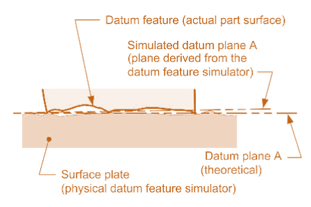
True Geometric Counterpart
Theoretical perfect boundary or best fit tangent plane of a specified datum feature.
Assumed to exist and simulated by inspection equipment.
Datum Feature Simulator
The inspection equipment used to establish and simulate a datum.
Feature Control Frame

A rectangular box divided into compartments containing geometric characteristic symbols, tolerance values, modifiers, and datum references.
First Compartment (Geometric Characteristic Portion)
Contains one of the 14 geometric characteristic symbols.
Second Compartment (Tolerance Portion)
Includes tolerance values and possible modifiers.
A diameter symbol (Ø) before the tolerance value indicates a cylindrical tolerance zone.
Without the diameter symbol, the tolerance zone can be parallel planes, parallel lines, or a uniform boundary (for profile tolerances).
The tolerance value represents the total tolerance.
Datum Reference Portion (Third, Fourth, and Fifth Compartments)
Used for specifying up to three datum references.
Feature Control Frame Types
Non-Datum Related Control
Contains two compartments (geometric characteristic + tolerance).
Datum Related Control
May have up to five compartments.
Common GD&T Symbols
GD&T employs a wide range of symbols to specify different geometric tolerances. Here are some common symbols and their applications:
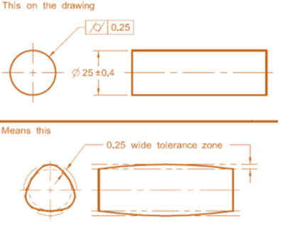
Straightness
Straightness of a Surface/Line


Straightness is a form tolerance in Geometric Dimensioning and Tolerancing (GD&T) that ensures a surface or line lies within two perfectly parallel lines. Unlike flatness, which applies to an entire surface, straightness applies to individual lines on a surface. The tolerance zone consists of two parallel lines that define the acceptable variation along a specific direction on the surface.
Straightness of a Feature of Size (FOS)

When straightness is applied to a feature of size (FOS), such as a shaft or pin, the tolerance zone becomes cylindrical rather than two parallel lines. This means that the axis of the feature must remain within a cylindrical tolerance zone of the specified diameter. This type of straightness tolerance ensures that rotating parts, such as shafts or pins, engage properly with their corresponding holes or bearings without excessive friction or interference.
Methods for Measuring Straightness
Dial Test Indicator (DTI) Method – Measures deviations along a single line by sweeping a probe incrementally to detect any out-of-tolerance variations.
Coordinate Measuring Machine (CMM) – Captures multiple data points along the feature length and analyzes deviations using software algorithms for high accuracy.
Optical or Laser Scanning Methods – Uses laser interferometers or optical profilometers for precise, non-contact straightness measurement, ideal for large components.
Flatness
Flatness of a Surface

Flatness is a form tolerance in Geometric Dimensioning and Tolerancing (GD&T) that ensures a surface remains within two perfectly parallel planes. The tolerance zone is defined by these planes, which are separated by the distance specified in the feature control frame. This tolerance is crucial in manufacturing to ensure uniform contact between mating surfaces, eliminating issues caused by waviness, irregularities, or warping.
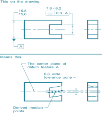
Flatness of a Feature of Size (FOS)

Flatness can also be applied to features of size (FOS), such as a large planar surface or a wide slot. In this case, the tolerance zone applies to the derived median plane—a theoretical plane created by taking the midpoints of corresponding opposite points along the feature’s surface. This ensures that the entire feature maintains a consistent flat profile, improving assembly and ensuring functional integrity in mechanical components.
Methods for Measuring Flatness
Dial Test Indicator (DTI) Method – Uses a mechanical probe to measure variations in surface flatness by referencing three predefined points.
Coordinate Measuring Machine (CMM) – Captures multiple data points with a probe and software to determine deviations from a perfect plane.
Optical or Laser Scanning Methods – Provides non-contact, high-precision surface mapping for industries requiring extremely tight tolerances.
Circularity

Circularity, also known as roundness, is a form tolerance in Geometric Dimensioning and Tolerancing (GD&T) that ensures a feature maintains a perfectly round shape in a single cross-section. The tolerance zone consists of two concentric circles, and the radial distance between them defines the acceptable variation in roundness.
Circularity of a Surface/Feature
When circularity is applied to a surface, it ensures that any cross-section of a round feature is within the tolerance zone. This tolerance is commonly used in shafts, pins, and cylindrical components where a consistent round profile is crucial for rotational balance and uniform wear.
Methods for Measuring Circularity
Dial Test Indicator (DTI) Method – Uses a probe on a rotating table to measure deviations at multiple points around the circumference, comparing them to circularity tolerance.
Coordinate Measuring Machine (CMM) – Captures multiple data points around the circular cross-section and analyzes deviations from a perfect circle for high-precision applications.
Roundness Tester / Polar Graph Method – Rotates the part while continuously measuring deviations, plotting the data on a polar graph for visual roundness analysis, commonly used in precision industries.
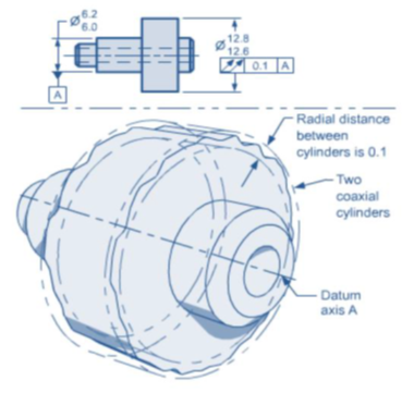
Cylindricity
Cylindricity is a form tolerance in Geometric Dimensioning and Tolerancing (GD&T) that ensures a feature maintains a perfect cylindrical shape along its entire length. The tolerance zone consists of two concentric cylinders whose radial distance defines the allowable variation.
Cylindricity of a Surface/Feature
When cylindricity is applied to a surface, it ensures that all points on the cylindrical surface remain within the tolerance zone. This is commonly used in shafts, pins, and rollers where a consistent cylindrical shape is critical for smooth rotation and precise fitment.
Methods for Measuring Cylindricity
Dial Test Indicator (DTI) Method – Measures variations along the cylindrical surface using a probe on a rotating spindle or V-blocks, identifying cylindricity defects beyond tolerance.
Coordinate Measuring Machine (CMM) – Collects multiple data points along the cylinder and analyzes deviations from the ideal shape, ensuring high accuracy for tight tolerance applications.
Roundness Tester / Polar Graph Method – Continuously measures deviations while rotating the part, creating a 3D profile of the actual cylindrical shape for detailed analysis.
Parallelism

Parallelism is a geometric tolerance in Geometric Dimensioning and Tolerancing (GD&T) that ensures a feature (surface or axis) is equidistant and consistently parallel to a reference datum. It controls the orientation of the feature, ensuring that it does not tilt or deviate from its intended parallel position.
Parallelism of a Surface
Surface parallelism is a geometric tolerance that ensures a flat surface remains parallel to a datum surface within a defined tolerance zone. This zone consists of two parallel planes, and all points on the surface must lie within it. It is commonly used in mating surfaces, sliding components, and sealing surfaces to maintain proper alignment and functionality.
Parallelism of an Axis (Feature of Size - FOS)

When parallelism is applied to a cylindrical feature, such as a shaft or pin, it ensures that the feature's axis remains parallel to a specified datum axis. The tolerance zone in this case is a cylindrical boundary surrounding the ideal axis, within which the actual axis must lie. This ensures proper alignment in assemblies, reducing wear and improving performance.
Methods for Measuring Parallelism
Dial Test Indicator (DTI) Method – Measures height deviations by moving a dial test indicator across the surface while the part rests on a datum simulator.
Coordinate Measuring Machine (CMM) Method – Uses a probe to take multiple measurements and software to check alignment with the theoretical parallel surface or axis.
Optical or Laser Scanning Method – Provides a non-contact, high-precision measurement using laser interferometers or optical profilometers.
Perpendicularity

Perpendicularity is a geometric tolerance in Geometric Dimensioning and Tolerancing (GD&T) that ensures a surface, axis, or feature is at an exact 90-degree angle (right angle) to a reference datum. It controls the orientation of a feature relative to another feature to ensure proper function and fit.
Perpendicularity of a Surface
Surface perpendicularity ensures a flat surface is exactly 90 degrees to a reference datum. It is defined by two parallel planes within a specified tolerance. This is crucial for components like mating surfaces, brackets, and mounting bases, where precise alignment is needed
Perpendicularity of an Axis (Feature of Size - FOS)

Axis perpendicularity ensures that the axis of a cylindrical feature, such as a hole, pin, or shaft, remains at a 90-degree angle to a reference datum. It is defined by a cylindrical tolerance zone surrounding the ideal axis, maintaining proper alignment and function in assemblies
Methods for Measuring Perpendicularity
Dial Test Indicator (DTI) Method: The part is placed against a datum simulator, and a dial test indicator checks deviations to ensure it meets tolerance limits.
Coordinate Measuring Machine (CMM) Method: A CMM probe captures data points, and software calculates deviation from a perfect 90° orientation.
Surface Plate and Height Gauge Method: The part is placed on a flat granite surface, and a height gauge measures deviations from 90°
Angularity

Angularity of a Surface or Feature
When angularity is applied to a surface, the tolerance zone consists of two parallel planes that are inclined at the specified angle relative to the datum. The entire surface must lie within this tolerance zone to be acceptable. This type of angularity tolerance ensures that surfaces mate properly and function as intended in mechanical assemblies.
Angularity of a Feature of Size (FOS)

When angularity is applied to a feature of size (FOS), such as a shaft, pin, or hole, the tolerance zone is cylindrical rather than two parallel planes. This means that the axis of the feature must remain within a cylindrical tolerance zone of the specified diameter. Angularity tolerance ensures that features are at a precise inclined angle to a datum, which is crucial for proper assembly and functionality.
Methods for Measuring Angularity
Sine Bar Method: The part is placed on a sine bar at a set angle, and a dial indicator checks deviations to ensure compliance with tolerance limits.
Coordinate Measuring Machine (CMM): A CMM probe collects data points, and software determines if the feature falls within the specified angularity tolerance.
Optical or Laser Scanning Methods: Laser interferometers or optical profilometers provide precise, non-contact measurements for large or high-precision components.
Position

Position tolerance in Geometric Dimensioning and Tolerancing (GD&T) controls the exact location of a feature, such as a hole, slot, or pin, relative to a datum reference. It ensures accurate placement within a defined tolerance zone, maintaining proper functionality and assembly fit. The true position of the feature represents its theoretically exact location, defined using basic dimensions enclosed in a rectangular box. For cylindrical features like holes, the tolerance zone is a cylindrical boundary around the true position, within which the feature’s axis or center point must remain. Position tolerance offers a more precise and functional alternative to traditional plus/minus tolerancing for locating features.
Methods for Measuring Position
Coordinate Measuring Machine (CMM) Uses a probe to collect data points and software to compare the actual position to the true position.
Optical/Vision System: High-resolution cameras and lasers provide non-contact measurement, ideal for delicate parts.
Dial Indicator & Gauge Blocks: A manual method where a dial indicator measures deviations from the true position.
Concentricity (In accordance with ASME Y14.5 - 2009)

Concentricity of a Feature of Size (FOS)
When concentricity is applied to a feature of size (FOS), such as a shaft or hole, it ensures that the median points of the feature's diameter remain within a specified cylindrical tolerance zone relative to a datum axis. Concentricity is a complex tolerance that controls the uniform distribution of a feature around a central axis, ensuring balanced rotation and minimal vibration
Methods for Measuring Concentricity
Coordinate Measuring Machine (CMM): Uses a probe to measure multiple points around the feature and analyzes if the median points align with the datum axis.
DTI Method: The part is rotated on a spindle while a dial indicator checks for any deviation from concentricity.
Optical/Laser Scanning: High-precision lasers or optical profilometers detect deviations from the ideal center axis.
Symmetry (In accordance with ASME Y14.5 - 2009)
Symmetry of a Feature of Size (FOS)
When symmetry is applied to a feature of size (FOS), such as a slot or a hole pattern, it ensures that the median points of the feature remain equidistant from a central datum plane. Symmetry is used to control the balance of a part and ensure uniform distribution around a centerline. Unlike concentricity, which deals with axes, symmetry applies to features measured relative to a central plane.
Methods for Measuring Symmetry:
Coordinate Measuring Machine (CMM): A probe collects data points along the feature’s surface and datum plane, analyzing median points for deviations from symmetry.
Optical/Laser Scanning: A high-resolution laser or optical scanner captures data, which is analyzed to check for symmetry deviations.
DTI Method: A dial test indicator measures deviations from the central datum, identifying any lack of symmetry.
Profile
Profile of a Surface

Profile tolerances in GD&T are highly versatile, as they can control form, orientation, and location simultaneously. The Profile of a Surface creates a tolerance zone that follows the shape of the entire surface, ensuring uniformity and precision. The width of this zone is determined by the specified tolerance value, defining acceptable variations in the surface contour. Depending on the application, profile tolerances can be applied with or without datums, allowing flexibility in controlling complex geometries.
Profile of a Line

The Profile of a Line in GD&T controls the shape of individual cross-sectional lines along a surface rather than the entire surface. It ensures that each cross-section conforms to the intended shape within the specified tolerance, maintaining accuracy in complex contours. This tolerance is commonly used in applications requiring precise shape control, such as aerodynamic surfaces and precision-machined components.
Methods for Measuring Profile
Coordinate Measuring Machine (CMM): Uses a probe to collect data points and compare them to the theoretical profile for high precision.
Optical or Laser Scanning: Non-contact method that creates a high-resolution 3D model to analyze deviations.
Comparator or Gauge Method: Uses mechanical templates or shadow graphs for quick inspections in production.
Runout:
Circular Runout
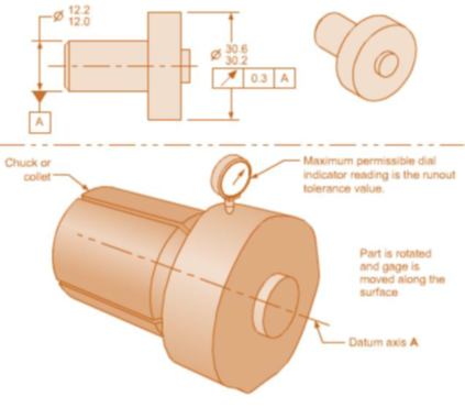
Circular Runout in GD&T controls the roundness of individual cross-sections of a feature relative to a datum axis. The tolerance zone consists of two concentric circles centered on the datum axis, ensuring minimal variation in roundness during rotation. Unlike circularity, circular runout requires a datum, meaning the tolerance zone is always referenced to a specific axis. This tolerance is crucial for rotating components like shafts, gears, and bearings to prevent wobbling and ensure smooth operation
Total Runout
Total Runout in GD&T controls both radial and axial deviations of a surface along its entire length relative to a datum axis. The tolerance zone consists of two concentric cylinders surrounding the datum axis, ensuring uniformity across the entire feature. Unlike circular runout, which applies to individual cross-sections, total runout is more restrictive as it governs the entire surface. This tolerance is essential for high-precision rotating components, such as spindles and rollers, to prevent excessive vibration and uneven wear.
Methods for Measuring Runout
Dial Test Indicator (DTI) Method: The part is rotated while a dial indicator measures deviations at various points to check for runout.
Coordinate Measuring Machine (CMM): A CMM probe collects data along the feature’s surface to analyze runout with high precision.
Roundness Tester: A specialized machine that rotates the part and records deviations using high-precision sensors.
GD&T and Industry Standards
GD&T is governed by various industry standards that provide guidelines and specifications for its application. Some important standards include:
ASME Y14.5: The ASME Y14.5 standard is widely used in North America and provides the rules and practices for dimensioning and tolerancing using GD&T. It covers topics such as datum referencing, geometric tolerances, and inspection methods.
ISO 1101: The ISO 1101 standard is an international standard that harmonizes GD&T practices across different countries. It provides guidelines for the interpretation and application of GD&T symbols.
AS9100: The AS9100 standard is specific to the aerospace industry and incorporates the requirements of ISO 9001 along with additional aerospace-related criteria. It emphasizes the use of GD&T for precise and reliable aerospace components.
Conclusion Fundamentals of GD&T
Geometric Dimensioning and Tolerancing (GD&T) is a powerful system that enables engineers and manufacturers to precisely define and communicate engineering tolerances. By using GD&T, companies can improve communication, enhance product quality, and optimize manufacturing processes. However, implementing GD&T comes with challenges related to knowledge, interpretation, and cost. Understanding and applying GD&T standards, such as ASME Y14.5 and ISO 1101, is essential for achieving consistent and effective use of GD&T across industries.
Frequently Asked Questions (FAQs)
1. What is the purpose of GD&T? GD&T serves the purpose of precisely defining and communicating engineering tolerances to ensure consistent interpretation and compliance throughout the product lifecycle. 2. How does GD&T improve product quality? By providing clear and unambiguous specifications, GD&T helps manufacturers produce parts that meet design requirements, resulting in improved fit, form, and function. 3. Can GD&T save costs in manufacturing? Yes, GD&T can lead to cost savings in manufacturing by allowing more flexibility in part tolerancing and enabling cost-effective production methods. 4. What are some common GD&T symbols? Common GD&T symbols include straightness, flatness, circularity, cylindricity, profile of a surface, concentricity, position, and runout. 5. How is GD&T inspected and measured? GD&T can be inspected and measured using various techniques, including Coordinate Measurement Machines (CMM), Optical Comparators, and Surface Plates with Height Gauges.
Comments